QS. Configuring and Launching MasterSCADA
Click the shortcut Start\Programs\MasterSCADA\MasterSCADA to open IDE; the project creation dialog is opened:
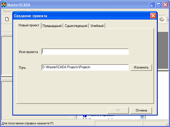
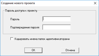
At the tab New Project of the Project Creation dialog, set ex as a name of the project being created, select (if required) a project folder, and click OK. The project access dialog is opened:
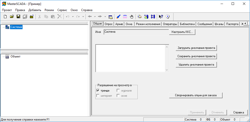
Keep the dialog fields empty and click OK. The project is created:
Click the menu command Service\Organizer\OPC DA servers:
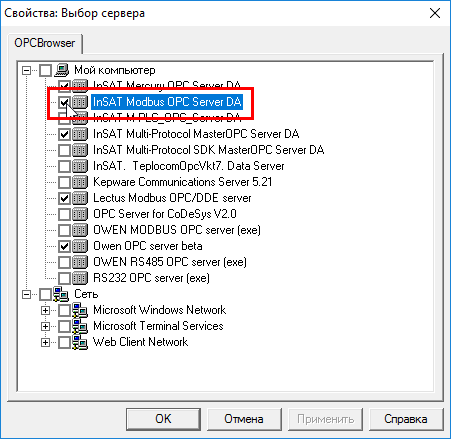
Upon this command, the dialog to select a server is displayed. In that dialog, select the InSAT Modbus OPC Server DA server (click to switch the flag 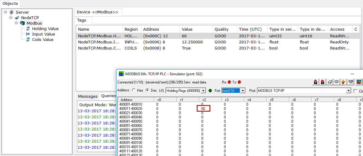 on the left of the server to the state
 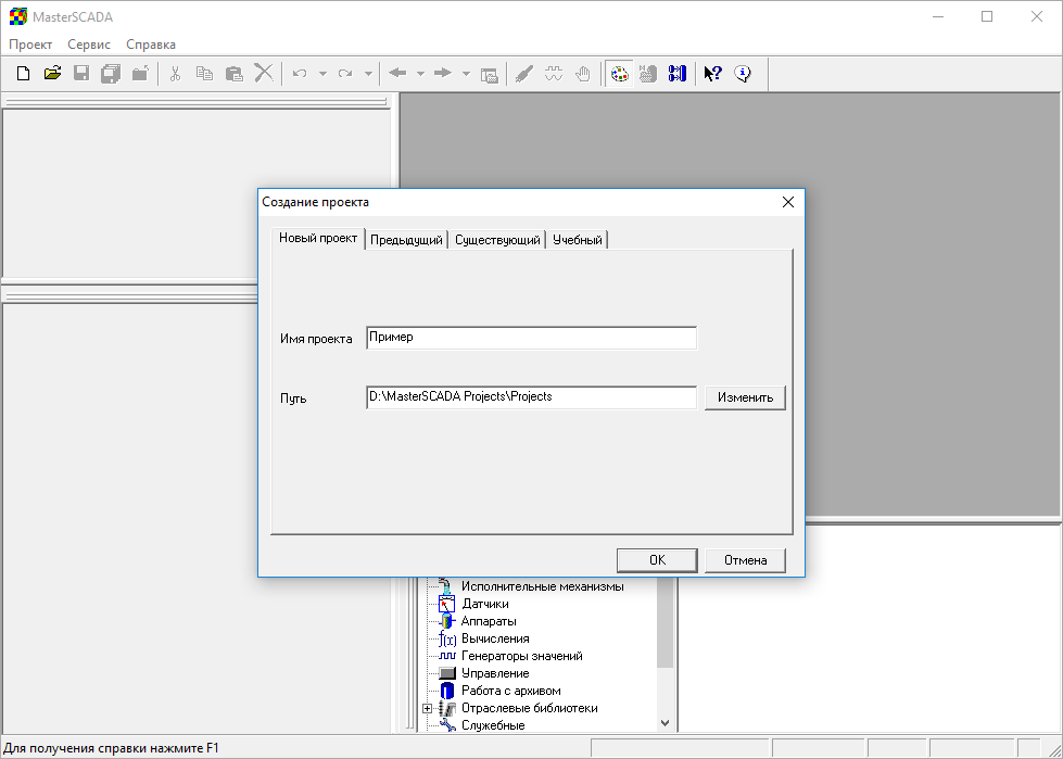 ):
):
Click the OK dialog button.
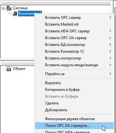
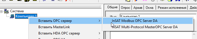
Right-click the System group, and, in the context menu displayed, execute the command Insert\Computer. In the System group, the Computer1 group is created:
Click the OPC servers group, and then, on the right, click the InSAT Modbus OPC Server DA server. The cursor takes on the form ![]() :
:
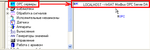
While the cursor has that form, click the Computer1 group. The InSAT Modbus OPC Server DA group is added to the system tree:
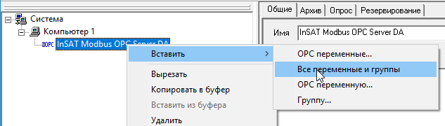
Right-click the InSAT Modbus OPC Server DA group, and, in the context menu displayed, click the command Insert\All variables and groups:
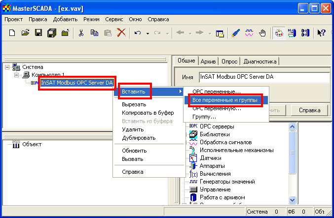
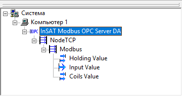
Now the system tree looks like
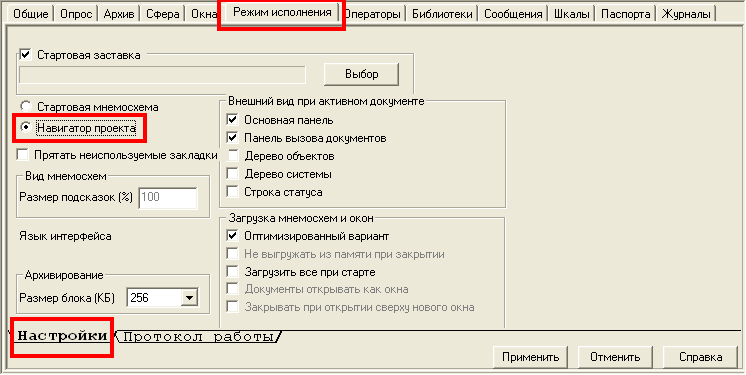
Click the System group, and, at the Execution mode tab of the Settings tab, click the Project explorer switch:
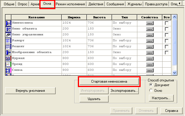
In the system tree, click the Computer1 group, and, at the Windows tab, click the Start mnemo button:
Upon this command, the start mnemo is opened in the editor. Drag all tags to that mnemo. As a result, graphic elements to display tag values are placed onto the mnemo:
To place a trend onto the mnemo, do the follows:
![]() In the Palette window, open the Windows tab, and click the Trend element in the list:
In the Palette window, open the Windows tab, and click the Trend element in the list:
![]() On the mnemo, click a point where the upper left trend corner must be positioned. As a result, the trend is placed:
On the mnemo, click a point where the upper left trend corner must be positioned. As a result, the trend is placed:
![]() One by one, drag the variables NodeTCP.Modbus.VAL and NodeTCP.Modbus.MAX onto the trend (as a result, the respective trend pens are configured):
One by one, drag the variables NodeTCP.Modbus.VAL and NodeTCP.Modbus.MAX onto the trend (as a result, the respective trend pens are configured):
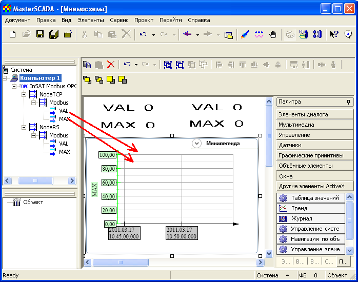
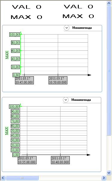
The same way, place one more trend onto the mnemo, and drag the tags NodeRS.Modbus.VAL and NodeRS.Modbus.MAX onto that trend. Now the mnemo looks like
Save project components (click the button ![]() of the toolbar) and the project itself (
of the toolbar) and the project itself ( ![]() ).
).
Click the menu command Project\Start:

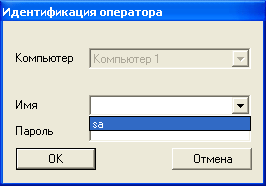
In the Operator identification dialog, select the sa operator and click OK:
In the Messages dialog displayed, click the Close button:

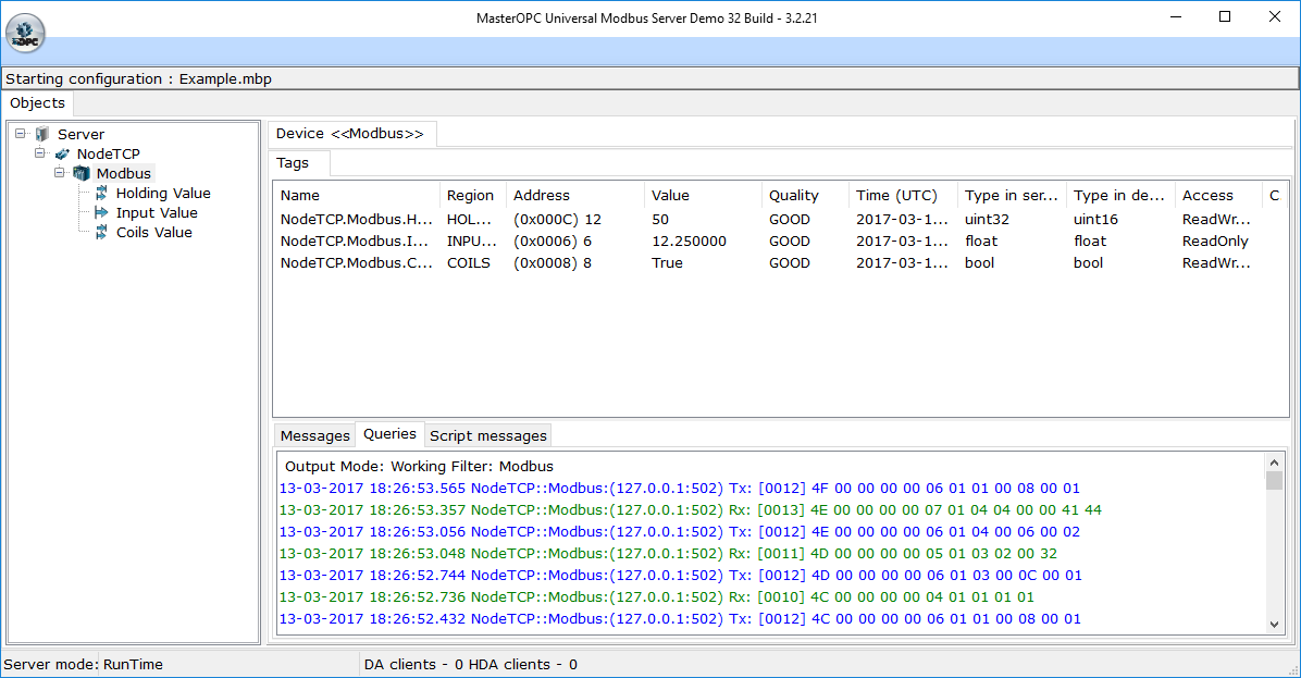
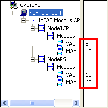
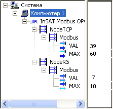
On the right of the system tree, the window to view/set values of variables is opened. That window displays the current values of the saw-shape signals (NodeTCP.Modbus.VAL and NodeRS.Modbus.VAL), and the upper limits of those signals (NodeTCP.Modbus.MAX and NodeRS.Modbus.MAX). All those values are received from the simulators of a Modbus TCP/IP device and a Modbus RTU device via the Modbus OPC Server server:
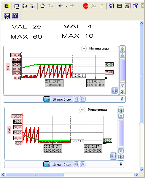
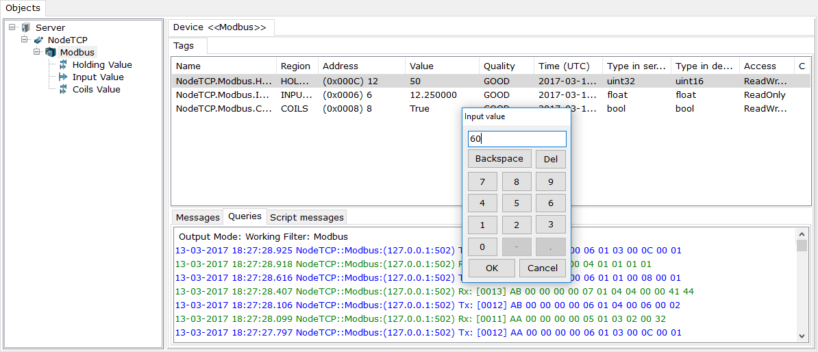
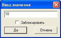
To check writing to the simulated devices, double-click a value of the NodeTCP.Modbus.MAX variable and, in the dialog opened, type 60 and click the Yes button:
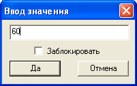
Then, double-click a value of the NodeRS.Modbus.MAX variable and, in the dialog opened, type 10 and click the Yes button:
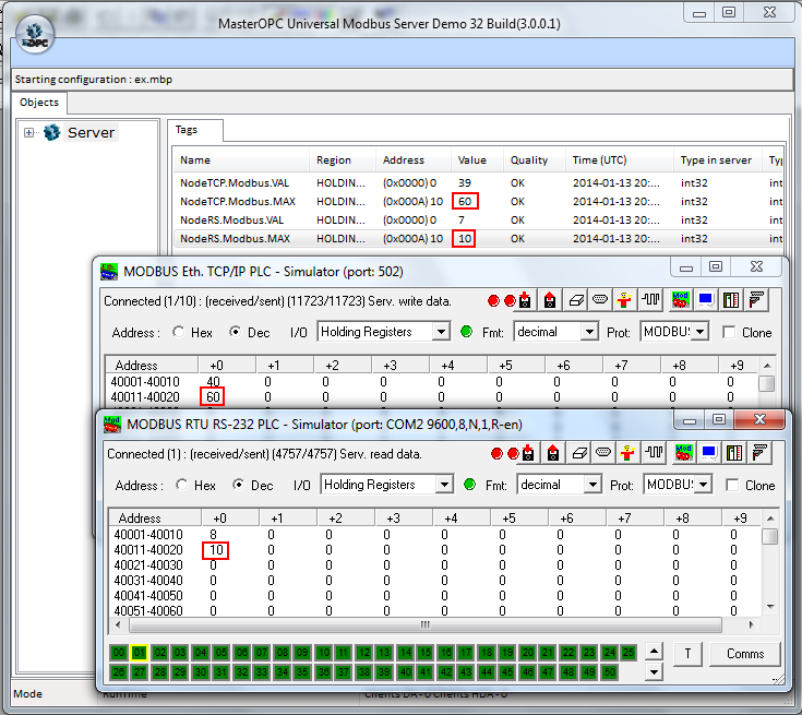
New values are displayed in MasterSCADA, in Modbus OPC Server and in the simulators:
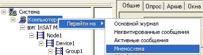
Right-click the Computer1 group, and, in the menu displayed, click the command Go to\Mnemo:
The mnemo elements and trends indicate the respective current values of the saw-shape signals and their upper limits: