![]() Switching the server to the run-time mode
Switching the server to the run-time mode
Click the shortcut MasterOPC Universal Modbus Server \MasterOPC Universal Modbus Server (the group MasterOPC Universal Modbus Server is situated in that folder of the Start menu that is chosen during the product installation), and, in the server control window, click the command ![]() New to create a new configuration:
New to create a new configuration:
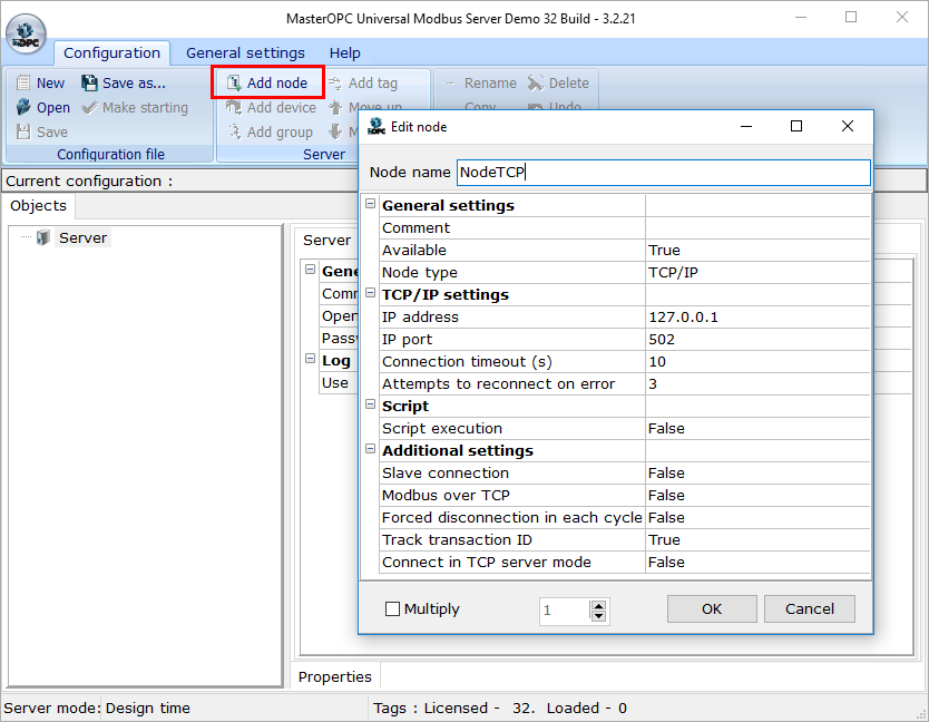
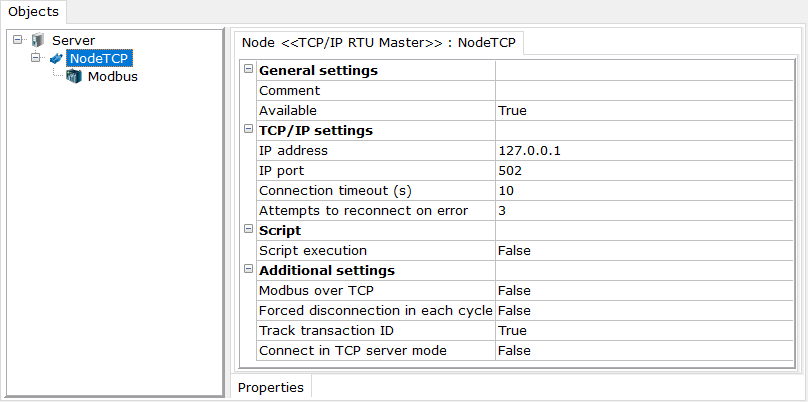
Click the root group Server at the tab Objects, click the command ![]() Add node from the menu, and, in the displayed dialog of node creation, set the following parameters: Node name – NodeTCP, Node type – TCP/IP. The main settings of a TCP/IP-type node are IP address and IP port. By default, the IP address 127.0.0.1 (an IP address of the local computer) and the port number 502 (the standard port of TCP/IP devices) are set. We will poll a local device simulator, therefore remain all parameters without changing; in real projects, you should specify an IP address of a remote controller.
Add node from the menu, and, in the displayed dialog of node creation, set the following parameters: Node name – NodeTCP, Node type – TCP/IP. The main settings of a TCP/IP-type node are IP address and IP port. By default, the IP address 127.0.0.1 (an IP address of the local computer) and the port number 502 (the standard port of TCP/IP devices) are set. We will poll a local device simulator, therefore remain all parameters without changing; in real projects, you should specify an IP address of a remote controller.
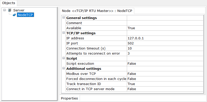
Click the OK button – the node created is added to the Server group at the Objects tab:
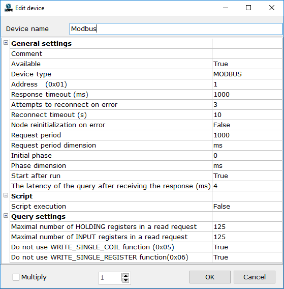
Click the group NodeTCP at the tab Objects, click the command ![]() Add device from the menu, and, in the displayed dialog of device creation, set the following parameters: Device name – Modbus, Device type – MODBUS, Request period – 1000. As a rule, a device address is 1 in Modbus TCP:
Add device from the menu, and, in the displayed dialog of device creation, set the following parameters: Device name – Modbus, Device type – MODBUS, Request period – 1000. As a rule, a device address is 1 in Modbus TCP:
Click the OK button – the created device is added to the NodeTCP group at the Objects tab:
Click the Modbus group of the NodeTCP group at the Objects tab, click the ![]() Add tag command from the menu, and, in the displayed dialog of tag creation, set the name Holding Value, and the register address 12. The Word data type specified in ModRSSim is equivalent to the uint16 data type, therefore select that type in the Data type in device section. Data type in server defines a data type of the tag in OPC clients; set this parameter to uint32.
Add tag command from the menu, and, in the displayed dialog of tag creation, set the name Holding Value, and the register address 12. The Word data type specified in ModRSSim is equivalent to the uint16 data type, therefore select that type in the Data type in device section. Data type in server defines a data type of the tag in OPC clients; set this parameter to uint32.
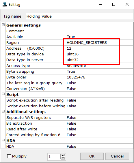
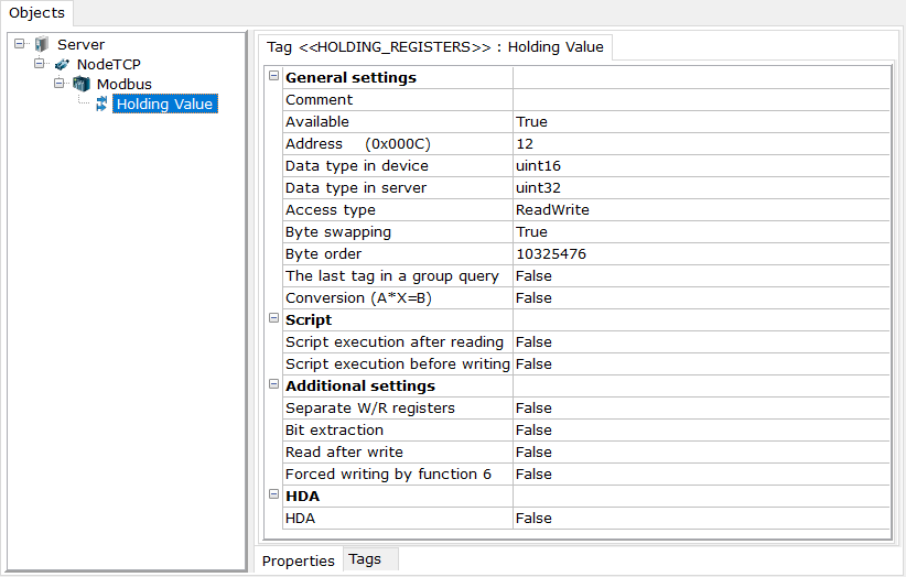
To complete tag creation, click the OK button - the tag is added to the device.
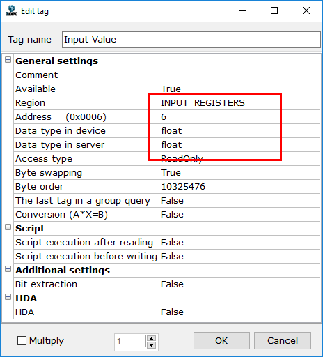
The same way, create the Input Registers tag. In settings, specify the region Input Registers, the address 6, and the data type float (both in server and device).
When using tags with a data type in device Float, Int32, Uint32 or Double, it is necessary to remember that swapping the bytes can be required. In the most cases, devices demand the following byte order:
int16, uint16 - the most significant byte first
Float, Int32, UIn32 - the most significant word first
Double - the most significant double word first
The special editor is provided for each tag to swap its bytes.
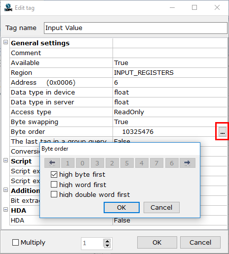
ModRSSim uses the "High byte first" permutation both for 2-byte and 4-byte numbers, therefore we do not need to change anything.
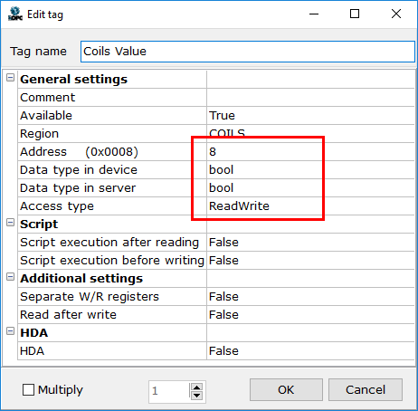
Now create the Coils tag.
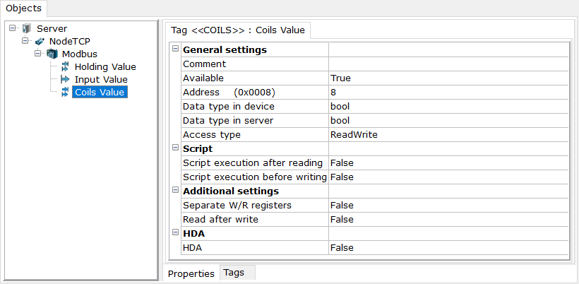
Thus, the tree contains 3 tags.
Switching the server to the run-tine mode
If the server is configured, it can be launched (that is, switched to the run-time mode). Click the ![]() Save as command from the server menu, set the Example name for the created configuration in the dialog displayed, and click Save. The Example.mbp file is created in the SERVERCFG folder, and the server window displays information about a file loaded. Next, click the
Save as command from the server menu, set the Example name for the created configuration in the dialog displayed, and click Save. The Example.mbp file is created in the SERVERCFG folder, and the server window displays information about a file loaded. Next, click the ![]() Make starting command from the server menu:
Make starting command from the server menu:
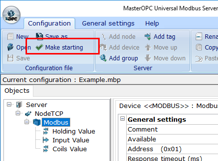
Note. If the Make starting command is disabled, you can run the server (see below) - this makes the configuration starting as well.
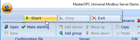
To switch the server to the mode of execution of the Example.mbp configuration, click the ![]() button, and, in the menu displayed, click the
button, and, in the menu displayed, click the ![]() Start button:
Start button:
In the run-time mode, the server window displays:
•At the Objects tab - the tree of devices and tags
•At the Tags tab - a list of tags of the selected element (device, group, sub-device) and their current values as well as timestamps and quality specifiers
•At the Messages tab - server messages
•At the Quaries tab - queries and device responses
•At the Script messages tab - messages from script (if they are programmed)
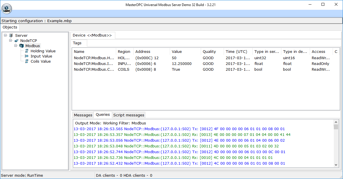
As we see, tags receive values, which we have inputted to the registers of ModRSSim.
The tags Holding Value and Coils Value have the access type ReadWrite, that is, the tags support writing. To check writing values from the server window to devices simulated, double click a line of the tag Holding Value at the tab Tags in the server window – the editor of changing a value is opened, and a current tag value is displayed in that editor. Input a new value in the editor.
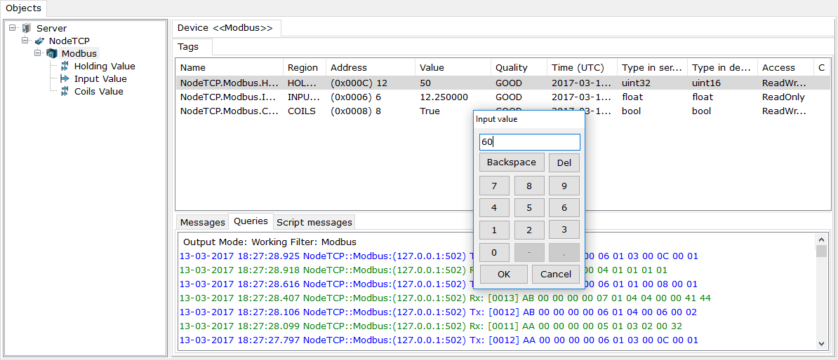
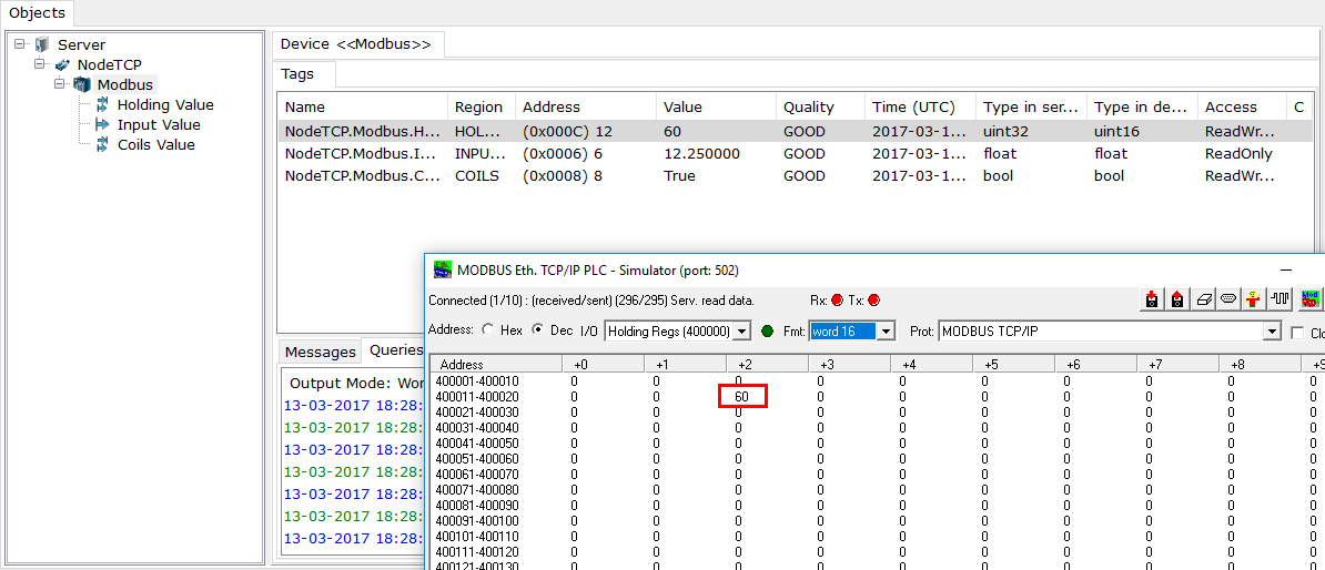
Upon the OK command, the value is written to the register of ModRSSim.
Now the OPC server is configured, and we can start to configure OPC clients.
According to the OPC standard, an OPC server is launched automatically when an OPC client subscribes to its values. Therefore you can close the OPC server (click the ![]() button again, and then click the Stop button). But you can remain the server in the run-time mode - an OPC client is successfully connected to the server as well.
button again, and then click the Stop button). But you can remain the server in the run-time mode - an OPC client is successfully connected to the server as well.
Note. If you remain the OPC server in the design-time mode, an OPC client can get a list of tags (they are added), but, when launching the client to the run-time mode, the OPC server is not launched; the "OPC server is suspended" flag is returned in this case.